
Introduction to CAN-BUS
What is CAN-BUS?
CAN stands for Controller Area Network, it is used to allow microcontrollers and devices to communicate with each other within a vehicle without a host computer which allows for control and data acquisition. These devices are also called Electronic Control Units (ECU) and they enable communication between all parts of a vehicle.
Today, you can find up to 70 ECUs in a modern car, e.g. the engine control unit, airbags, audio system, etc. CAN is a serial communication bus designed for industrial and automotive applications. For example, they are found in vehicles, farming equipment, industrial environments, etc.
How does CAN-BUS work?
The fuel level, door sensors, odometer, and many more parts of a car have to communicate with each other somehow, and CAN BUS is what they used to do. These CAN-compatible components, which are called “nodes” are connected with a 3-string copper wire, with no central router to govern the flow of data. Every node can hear the messages of every other node.
Every node has an ID, where the ones with the higher priority ID can have the priority to “talk” first while the others “listen”. This is to ensure that there are never two nodes talking at the same time. The biggest benefit of CAN-BUS is to be able to just connect components without having to worry about signal routing.
Why use the CAN protocol rather than UART, SPI, and I2C?
Compared to other communication protocols like UART, SPI, and I2C, using the CAN protocol is much more reliable as they are standard automotive communication protocols that are used to transmit vital data like a throttle position in a vehicle. If miscommunication or loss of data occurs, it could lead to critical failures.
In a vehicle, safety and reliability are the two most valued features. CAN-BUS is therefore the ideal protocol for vehicular usage.
The CAN bus standard is used in practically all vehicles and many machines due to below key benefits:
Low Cost
- With its multiplex wiring that combines analog and digital signals and their transmission over a shared medium, it reduces the amount of wiring needed, errors, and weight.
- When adding or reducing some equipment, it can be easily operated, and there is no need to carry out a large-scale transformation of the system, which saves a lot of manpower and costs.
Centralized
- As CAN-BUS supports centralized control over electronic devices that are connected to the network, it enables central diagnostics, data logging, and configuration.
- Error handling is also built into the CAN protocol where nodes can check for errors in transmission while maintaining their own error counter. For example, the protocol supports different error detection capabilities such as bit error, ack error, form error, CRC error, etc.
Flexible
- As each CAN-connected ECU can receive all transmitted messages, it can also decide whether it is relevant and act accordingly.
- The CAN protocol is also a message-based communication protocol where nodes on the bus have no identifying information.
- With the above features, nodes can easily be added or removed and modified.
- For beginners, it will be easy to integrate new electronic devices into the CAN-BUS network without any significant programming overhead.
Robust
- When choosing a communication protocol, durability and reliability are very important. You would want your communication protocol to be self-sustaining and durable for a long period of time without maintenance.
- With the CAN BUS, the system is robust towards electric disturbances and electromagnetic interference-ideal for safety-critical applications (e.g. vehicles).
Efficient
- CAN messages frames are prioritized by ID where the top priority will get bus access and yet frames would not be interrupted.
- Flash programming, also saves time together with less and simple wiring.
The role of CAN
What will happen if there is no CAN in the car?
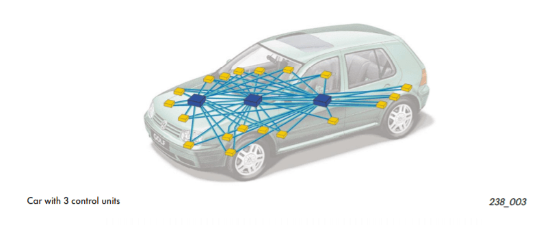
Without the CAN protocol, electronic modules in vehicles will have to communicate with each other using direct, point-to-point analog signal lines. It is not only time-consuming but also a messy excessive amount of wiring as seen in the picture above if each module requires a direct line connected for communication. Besides, there may be unreliable communication between devices. Excessive wires may require additional equipment, which also creates cost issues.
What will happen if there is a CAN in the car?
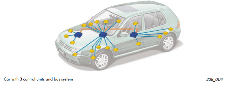
With CAN protocol, it eliminates the need for all these wirings by enabling electronic devices to communicate with each other with a single multiplex wire that connects each node in the network to the main dashboard as seen in the picture above.
The multiplex wire and architecture enable signals to be combined and transmitted over the entire network with just a single wire while ensuring each electronic module in vehicles receives data from sensors and actuators. This allows the user to be able to connect any number of ECUs in your vehicle through the two-wire bus.
It also allows for several features to be added via just software. Furthermore, an ECU is able to use data from another ECU which eliminates the need to install the same sensors in multiple devices.
CAN-BUS Wiring Sequence
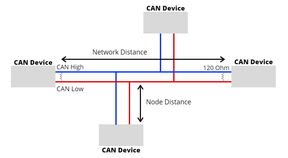
- The CAN protocol consists of two wires for bi-directional data transmission as shown above which are
- CAN_H (CAN High)
- CAN_L (CAN Low)
- The wires act as a differential line which means the CAN signal either 0 or 1, can be represented by the potential difference between the two wires
- When the CAN bus is in idle mode, both lines carry 2.5V. When data bits are being transmitted, the CAN high line goes to 3.75V, and the CAN low drops to 1.25V, thereby generating a 2.5V differential between the lines.
- For CAN termination, as you can see from the picture above, a single 120 Ohm is generally used at the 2 ends of the CAN network.
CAN Protocol Speed and Range
- Communication speeds of the CAN protocol range from 10kpbs to 1Mbps.
- The speed also depends on the length of wire used. The shorter it is, the faster the communication speed, and the longer it is, the slower the communication speed.
- For example, at 40 meters, the speed will be at 1Mbps. At 1000 meters, the speed can be at 50kpbs.
- The node distance is generally advised to be no more than 0.3 meters / 1 foot.
CAN Message
- To fully understand how the CAN protocol works, let us look at the frames sent over the network.
- The CAN message contains many segments. The 2 main segments, identifier, and data will be the ones transmitting the data.
- The identifier is used to identify CAN devices in a CAN network while data will be the sensor or control data that have to be sent from one device to another.
- The identifier or CAN ID is either 11 or 29 bits in length depending on the type of CAN protocol used.
- Standard CAN = 11 bit
- Extended CAN = 29 CAN
- While the data can be anywhere from 0 to 8 bytes.
